

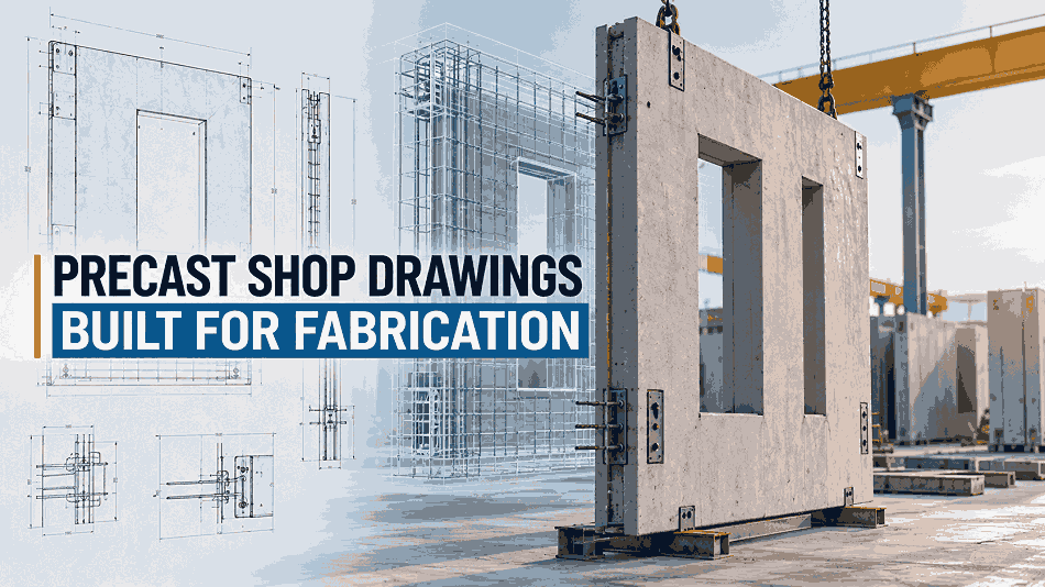
A precast shop drawing is more than a detailed representation of a concrete element. It is the link between design intent and actual fabrication. If that link is unclear, even a well-designed precast project can face rework, fabrication delays, RFIs, and installation problems.
A truly fabrication-ready shop drawing gives the fabricator the information needed to build the element accurately and confidently. It brings together geometry, reinforcement, embeds, connections, tolerances, and coordination details into one clear document. But what separates a drawing that is simply detailed from one that is genuinely ready for fabrication?
Read more on Cast Stone Joint Detailing Failures
It Starts With Complete and Accurate Geometry
The first requirement is straightforward: the physical shape of the precast element must be clearly defined.
Overall dimensions are important, but they are only the beginning. Openings, recesses, reveals, slopes, offsets, bearing locations, connection zones, and other architectural or structural features must also be accurately represented. For complicated elements, a single elevation is rarely enough. Plans, sections, details, and enlarged views may be needed to communicate how different components come together.
The objective is simple: the fabricator should not have to interpret what the finished piece is supposed to look like.
Reinforcement and Embeds Must Be Coordinated
One of the most common challenges in precast detailing is the interaction between reinforcement and embedded components. A drawing may show the reinforcement correctly and the embeds correctly, yet the two may not physically work together once placed inside the element. Lifting inserts, plates, sleeves, anchors, and connection hardware can all compete for space with reinforcement.
A fabrication-ready drawing considers these relationships before the element reaches the casting bed.
It should clearly communicate:
- Reinforcement size, spacing, shape, and location
- Concrete cover and relevant clearances
- Embed type, dimensions, and exact position
- Openings, sleeves, and penetrations
- Lifting and handling components
- Connection hardware and interfaces
This is where experienced precast detailing makes a real difference. The goal is not simply to document each component but to ensure that all components can coexist within the finished element.
Connections Need More Than a Symbol on a Drawing
Precast elements eventually have to connect to something else—steel, concrete, foundations, slabs, walls, or other precast members. That makes connection detailing particularly important.
A fabrication-ready drawing should clearly show the location and orientation of connection components and provide the information necessary for them to be incorporated during manufacturing. If an embedded plate is even slightly misplaced, the problem may not become visible until the element reaches the jobsite.
At that stage, correcting the issue can involve additional engineering, field modification, crane time, and installation delays. Good detailing addresses these issues while they are still on the screen.
Tolerances Matter
Precast construction depends on accurate manufacturing, but no physical process is completely free from variation. Formwork, casting, stripping, handling, transportation, and erection can all introduce dimensional differences.
That is why tolerances should be considered as part of the detailing process, not added at the end. A single element may be within its permitted tolerance and still create a problem when combined with several adjacent elements. This is particularly important around structural connections, bearing conditions, openings, and façade interfaces.
Daiden’s BIM-based precast approach focuses on identifying geometric conflicts and tolerance-related issues before fabrication, helping move problem-solving from the jobsite into the digital coordination stage.
A Fabrication Drawing Should Also Think Beyond the Factory
The precast element has a journey after it is manufactured. It has to be stripped from the mould, lifted, stored, transported, and eventually erected. That means fabrication-ready documentation needs to consider handling and erection as well as production. Piece marks, lifting information, hardware, orientation, and erection references should remain consistent across the relevant drawings and schedules. When this information is coordinated properly, the same element can be tracked from fabrication through delivery and installation.
This is especially valuable on large projects where hundreds of individual precast pieces may look similar but have different dimensions, connections, or locations.
Coordination Is What Turns Detail Into Confidence
Modern precast projects often involve architectural, structural, MEP, and other disciplines. Each may provide accurate information independently, but conflicts can still occur when those requirements occupy the same physical space.
For example, a mechanical penetration could interfere with reinforcement, or an architectural reveal could conflict with an embedded connection. BIM and 3D coordination can expose these conflicts before fabrication begins. Instead of discovering the issue when concrete has already been cast, the team can resolve it while changes are still relatively simple.
This is an important part of Daiden Global Design’s approach, combining precast detailing with BIM-based coordination to support accurate and buildable project documentation.
The Final Test: Can the Fabricator Build It Without Guesswork?
Ultimately, a fabrication-ready shop drawing should answer the practical questions that arise on the production floor.
Can the team understand the element’s geometry? Can they place the reinforcement and embeds correctly? Are the connection requirements clear? Are the relevant tolerances understood? Can the piece be identified and coordinated with erection documentation?
If the answer is yes, the drawing has achieved its purpose.
A good shop drawing does not simply contain more information. It contains the right information, clearly coordinated and presented in a way that supports fabrication.
From Design to Fabrication With Daiden Global Design
At Daiden Global Design, precast detailing is approached as more than a drafting exercise. Our team develops shop drawings, erection documentation, reinforcement details, embed and hardware details, piece tickets, mould details, and related fabrication documents with a focus on accuracy and coordination.
With experience supporting projects across different building types and international markets, Daiden combines detailing expertise with BIM and structured QA processes to help clients move from design information to fabrication-ready documentation.
Because in precast construction, the best shop drawing is not simply the one that looks complete.
It is the one that can be taken to the factory and built correctly the first time.
Contact us: https://www.daidenglobal.com/contact/