

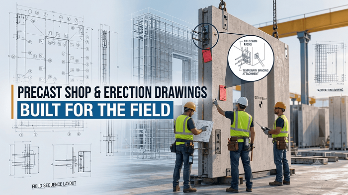
Shop Drawings vs. Erection Drawings: The Core Disconnect
While shop drawings focus on how individual pieces are manufactured reinforcing steel placement, mix designs, dimensions, embedded plates, and architectural finishes erection drawings are entirely about spatial context, staging, and sequence.
A shop drawing tells a plant worker how to build a single panel or cast stone lintel. An erection drawing tells the ironworker or rigger where that piece goes, how it connects to the structural frame, and the exact order in which it must arrive and be installed.
When erection drawings merely repurpose shop drawings without added field data, install crews face severe operational challenges.
Read more on : What Makes a Precast Shop Drawing Truly Fabrication-Ready?
What Your Install Crew Desperately Needs (That Shop Drawings Miss)
1. Clear Sequencing and Piece Mark Mapping
Shop drawings often group panels by type or mould, leading to piece marks scattered randomly across sheets. Field crews working under tight crane rentals need a logical, sequence-driven erection plan.
-
What erection drawings should show: Clear phasing, elevation zones, crane pick sequences, and prominent piece-mark callouts that correspond directly with delivery truck bundling.
2. Connection Details in Structural Context
A shop drawing shows an embedded plate and anchor details in isolation. In the field, connection points interact with structural steel, cast-in-place concrete, or backup stud walls often with field tolerances coming into play.
-
What erection drawings should show: Isometric blow-ups of complex connections, weld sizes, shim pack locations, bolt torque specifications, and clear tolerances for adjustment in three dimensions (X, Y, and Z axes).
3. Temporary Bracing and Shoring Requirements
Precast panels and heavy cast stone veneers are inherently unstable until fully tied into the primary structure. Shop drawings rarely account for temporary wind loads or intermediate shoring phases.
-
What erection drawings should show: Specific locations for temporary wind braces, compression struts, shoring tower placements, and the minimum required structural connections before a crane can safely unrig a piece.
4. Rigging, Center of Gravity, and Lifting Data
Rigging safety depends entirely on knowing how a piece behaves when suspended. Standard architectural dimensions don’t indicate weight distribution or eccentric loads.
-
What erection drawings should show: Exact piece weights, center of gravity markers for asymmetric panels, designated lifting insert locations, and approved rigging configurations to prevent panel cracking or sling slip.
5. Field Dimensions vs. Nominal Dimensions
Fabrication happens in a controlled plant environment where millimetre precision rules. The real world of structural frames involves camber, foundation settlement, and thermal movement.
-
What erection drawings should show: Critical field-verify dimensions, maximum allowable joint tolerances, sealant joint widths, and flashing interface details so installers know how to absorb cumulative dimensional variance.
Bridging the Gap for Flawless Execution
For general contractors, precast manufacturers, and installation subcontractors, investing in comprehensive, field-ready erection drawings is the ultimate insurance policy against costly rework, crane downtime, and safety incidents. By providing installers with the operational roadmap they need, you transform a chaotic job site into a synchronized, highly efficient operation.
Check here how to Know more about Precast Detailing Services!